Blog
Baking Linear Deformation into Vertex Colors from Houdini to Unreal WPO
Quick Intro
For simple State A → State B mesh deformation, you can bake the vertex movement directly into the mesh instead of relying on bones or Vertex Animation Textures (VAT).
The workflow is straightforward:
Houdini calculates the vertex offset → stores XYZ in Vertex Color RGB → Unreal reconstructs the deformation using WPO.
The Houdini side stays procedural, and the Unreal setup is controlled with a single material parameter.
Houdini
Start with the original mesh and its deformed state. Both need matching topology and point order, so each point refers to the same part of the mesh.
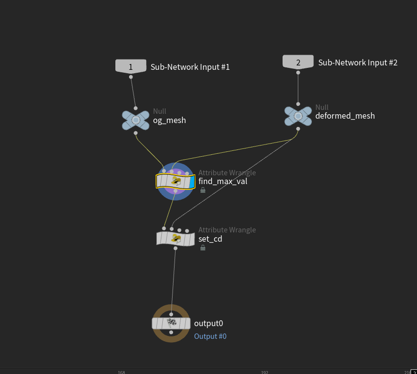
find_max_val — Run Over: Detail (only once)
Connect og_mesh to input 0 and deformed_mesh to input 1. This wrangle finds the largest absolute displacement component across X, Y and Z and stores it as max_diff_val.
// OG mesh in input 0, deformed in 1
float max_val = 0.0;

int npts = npoints(0);
for (int i = 0; i < npts; i++) {
    vector posA = point(0, "P", i);
    vector posB = point(1, "P", i);
    vector diff = posA - posB;

    max_val = max(max_val, abs(diff.x));
    max_val = max(max_val, abs(diff.y));
    max_val = max(max_val, abs(diff.z));
}

setdetailattrib(0, "max_diff_val", max_val, "set");
The sign doesn’t matter for this step because we’re measuring absolute values. One shared maximum gives every point the same encoding range.
set_cd — Run Over: Points
Connect find_max_val to input 0 and deformed_mesh to input 1. Here the direction matters: use deformed − original so a positive BlendTime moves the exported rest mesh towards its deformed state.
vector diff = point(1, "P", @ptnum) - @P;
float max_val = detail(0, "max_diff_val", 0);

// Encode signed displacement into the 0-1 color range.
// Identical meshes have no displacement, so avoid dividing by zero.
@Cd = set(0.5, 0.5, 0.5);
if (max_val > 0.0) {
    diff /= (max_val * 2.0);
    @Cd = diff + 0.5;
}

// Store the Unreal value separately; Houdini units here are metres.
if (@ptnum == 0) {
    setdetailattrib(0, "max_diff_val_unreal", max_val * 100.0, "set");
}
RGB now stores the XYZ offset: 0.5 represents no movement, values below it represent negative movement, and values above it represent positive movement.
The × 100 converts metres to Unreal’s centimetres. It assumes the mesh is exported with the same metre-to-centimetre conversion; adjust this factor if your pipeline uses different units. Copy max_diff_val_unreal from the Geometry Spreadsheet’s Detail view into the material’s maxDistance parameter. This custom detail attribute isn’t automatically connected to the material.
Export the rest mesh with its baked colors. In Unreal, import those vertex colors rather than ignoring or overriding them.
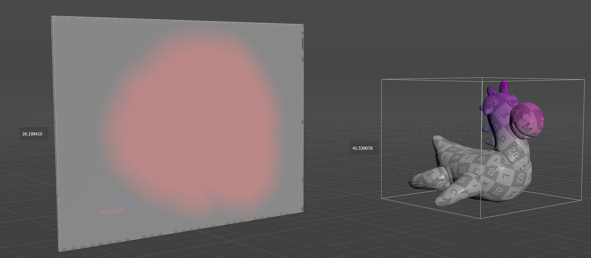
The displayed values—26.198410 for the wall and 41.539078 for the toy—are each mesh’s maximum displacement in centimetres (max_diff_val_unreal in the wrangle above). Enter the corresponding value into the maxDistance parameter of that mesh’s Material Instance.
Unreal
On the Unreal side, first swizzle RGB to RBG, as shown by the Make Vector3 node in the graph, then reverse the encoding:
LocalOffset = (VertexColor.rbg - 0.5) * (maxDistance * 2)
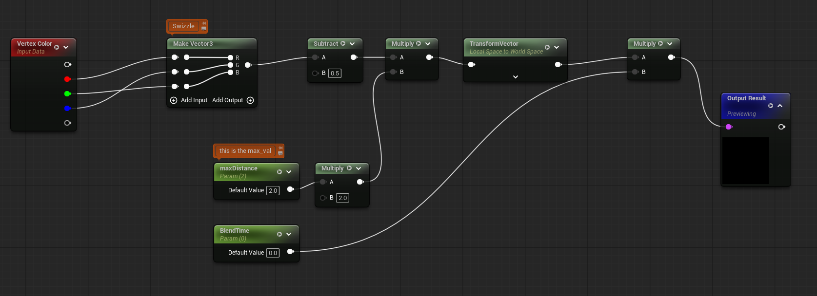
Material Function setup
Houdini uses Y-up, while Unreal uses Z-up. In this setup, the baked Houdini XYZ displacement needs to become Unreal XZY:
That’s why Make Vector3 receives R, B, G. A vertical movement stored in Houdini’s green channel must drive Unreal’s Z axis.
The mesh import handles the geometry’s coordinate conversion, but RGB travels as color data—the importer doesn’t know it contains a displacement vector. We perform that conversion ourselves. This swizzle matches the setup shown; it must agree with your export/import axis settings. If you already converted the offsets before baking them, don’t swap them again.
Transform the decoded vector from Local Space → World Space, multiply it by BlendTime, and connect it to World Position Offset.
BlendTime = 0 → original mesh
BlendTime = 1 → fully deformed mesh
Drive it from a Material Instance, Blueprint, Sequencer or Niagara. And that’s pretty much it.
Results
The mesh carries its own deformation data. There are no animation textures or skeletal animation assets, just the baked offsets and the material that reconstructs them.
That doesn’t automatically make it faster than VAT or other approaches. WPO cost depends on mesh density, material complexity and rendering path, particularly for Nanite versus non-Nanite workflows. Profile it in the context where it will actually be used.
Pros & Cons
| Pros | Cons |
|---|---|
| Simple, procedural Houdini → Unreal pipeline | Vertices follow straight paths between states; this doesn’t preserve a curved or rotation-driven motion |
| Deformation data stays with the mesh | Shape quality depends on vertex density, and precision depends on the vertex-color storage and encoding range |
| No additional animation textures | Normals do not update |
| One blend parameter to expose to gameplay | Uses RGB channels that may already be needed for other data |
| Good fit for A → B deformation | WPO cost needs profiling for Nanite and non-Nanite assets |
| — | Large offsets need appropriate bounds; Nanite also needs attention to its WPO displacement limits |
| — | WPO doesn’t update collision to match the deformed surface |
| — | Not a replacement for VAT when you need a multi-frame deformation |
Use Cases
This works best when the deformation can be described as “move these vertices from here to there.”
Compressing props, predefined damage states, simple bending and gameplay-driven shape changes are good candidates—as long as the straight-line transition looks right.
Concrete example : Melting candles/props, Engine Thrusters expanding or shrinking (see Ship Thrusters when accelerating) or Deflation of air filled props (tires, ballons, etc)
For simple linear deformation, it’s a compact workflow that is easy to generate in Houdini and easy to control in Unreal.
/Andrei